Surface geochemistry sampling
Pre-survey considerations
The collection of marine sediment cores for regional petroleum system evaluation has evolved as the sampling, geophysical and navigation tools have become more powerful, and our understanding of migration and near-surface processes have developed. The early days of grid surveys with shallow cores (<1 m) and no real-time seismic data have been replaced by:
- sophisticated pre-survey seismic programs to identify major migration pathways and evidence of leakage (e.g. faults penetrating seabed, pock marks, gas chimneys and out-cropping strata)
- remote sensing seep surveys
- real time seismic to locate core sites during coring operations
- deeper coring equipment to sample below the oxic/anoxic boundary
- better navigation in conjunction with subsurface locating devices to position more accurately the core body within the targeted feature
Pre-planning is now considered critical to ensure the offshore geochemical survey is safe, productive and has a good chance of providing positive results.
Core site selection
Seabed geochemical cores can be collected using a grid spacing pattern over the area of interest or may be site specific where selected features of interest are targeted. The latter is preferred when possible. Grid surveys are undertaken assuming the petroleum leakage is near vertical, resulting in a surface pattern reflective of a subsurface petroleum accumulation.
The resulting near-surface geochemical measurements are contoured in the hopes of finding a surface pattern related to the entrapped petroleum accumulation. The apical or halo surface geochemical anomaly is then used as evidence that a charged petroleum trap is present.
The most common approach in offshore seabed geochemical surveys is to target major migration pathways, which may contain evidence of hydrocarbon leakage. This approach has been called site specific by Abrams (1992, 1996), and has been the preferred approach by most companies/contractors since the early nineties.
Petroleum from subsurface accumulations, or a mature source rock, will leak preferentially via buoyancy driven forces along major cross-stratal breakage (i.e. faults), or along major fluid flow pathways (hydrodynamic), to near-surface sediments.
The leaking hydrocarbons can cause seismic expression (acoustic anomalies) and/or seabed morphological features, depending on the hydrocarbon phase, leakage rates and volume, as well as sediment type. The morphological features, which should be the focus for sampling, include:
- pockmarks (seabed depression)
- seabed hardgrounds (carbonate)
- subsurface hardgrounds (hrdz)
- wipe-out zones, also known as gas chimneys or acoustic blanking (reflection discontinuity and amplitude-loss creating distortion zones)
- BSR (bottom simulating reflector, gas hydrate related)
- water column gas anomalies (haloes)
- near-surface bright spots
- shallow pull downs (slow-down signal due to gas)
A map of surface and/or near-surface features should be made to evaluate the distribution of these anomalies relative to regional geology and basin features (deep source candidates, identified traps, DHI’s etc).
Based on the above, the following key recommendations can be made:
- choose a variety of target features and geographical areas
- target features should be potential major migration pathways from deep within the sedimentary section to near-surface
- prioritise potential migration pathways with seismic evidence of near-surface hydrocarbon leakage
Providers of services and technologies for surface prospecting are provided in the following tables:
Suppliers of surface exploration services/technologies
| Company | Services | Location | Phone | Website | |
|---|---|---|---|---|---|
| Fugro Geolab Nor AS | Off-shore HC sampling & heat flow studies & geochem analyses | Trondheim Norway | +4773964000 | via website | http://www.fugro.com/ |
| CGG (Robertson) | Seep Explorer (GOSD) & GLOGOS seep databases | via website | http://www.cgg.com/en/What-We-Do | ||
| TDI-Brooks International Ltd | Off-shore HC sampling & heat flow studies & geochem analyses | College Station TX | +19796933446 | Drjmbrooks@aol.com | http://www.tdi-bi.com/ |
| Geochemical Solutions International | Geochemical coring surveys & spec survey | Shenandoah TX | +12813640661 | via website | http://www.geochemsol.com/ |
| Pace Analytical Microseeps | Geochemical sampling, analytical | Pittsburgh PA | +18006592887 | via website | http://www.microseeps.com/ |
| Fugro Alluvial Offshore Ltd | Geochemical sampling | Glasgow; Great Yarmouth UK | +441493440320 | http://www.alluvial.co.uk/ | |
| Selantic Subsea AS | Geochemical sampling | Bergen Norway | +4755927300 | subsea@selantic.com | http://www.selantic.com/ |
| Chem Terra International | Onshore prospecting & direct HC methods | Calgary Canada; Germany | +4032621747 +4924718479 | http://www.chemterra.com/ | |
| GeoFrontiers Corporation | Onshore soil sampling | Rowlett TX | +19724127939 | http://www.geofrontiers.com/ | |
| Vista Geoscience | Soil gas samples | Golden, Colorado | +13032771694 | via website | http://www.vistageoscience.com/exp |
| Amplified Geochemical Imaging LLC | Direct HC sampling via Goresorber | Newark NJ | +13022662428 | http://www.agisurveys.net/ | |
| GeoChemTech Inc | Geochemical surveys using Goresorber | Calgary, Canada | +4038639738 | http://www.geochemtech.ca/ | |
| Exploration Technologies Inc | Direct detection | Houston TX | +12815304300 | etimail@eti-geochemistry.com | http://www.eti-geochemistry.com/ |
| MicroPro GmbH | Microbial surveys | Gommern, Germany | +493920070310 | info@micropro.de | http://www.microprolabs.de/ |
| Environmental BioTechnologies Inc | Microbial surveys | San Carlos CA | +12093334570 | ebt@e-b-t.com | http://www.e-b-t.com/ |
| Geo-Microbial Technologies | Surface microbial & HC surveys | Ochelata OK | +19185352281 | danielh@gmtgeochem.com | http://www.gmtgeochem.com/ |
| GrayStone Exploration Labs Inc | Iodine analysis for HC exploration | Golden CO | +13032783252 | chuck@graystonelabs.com | http://www.graystonelabs.com/ |
| Isotech Laboratories Inc | Supplier of Iso-jars & iso-tubes | Champaign IL | +18773624190 | http://www.isotechlabs.com/ | |
| Geotech (US Geochemical) | Info site for surface geochem analogs, images, bibliographies | Littleton CO | +17204456455 | http://www.geotech.org/ |
Remote sensing sources (satellites)
| Technique | Organisation | Features |
|---|---|---|
RADARSAT http://www4.asc-csa.gc.ca/auot-eoau/eng/eoadp/Projects/73136.aspx | Canadian Space Agency (CSA) |
|
NOAA Satellite Series: AVHRR, MODIS sensors http://modis.gsfc.nasa.gov/ | NOAA-National Oceanic and Atmospheric Administration |
|
IRS http://www.fas.org/spp/guide/india/earth/irs.htm | Indian Space Research Organization (ISRO) |
|
ENVISAT http://earth.esa.int/satconc2 | European Space Agency (ESA) |
|
LandSat Thematic Mapper http://landsat.gsfc.nasa.gov | NASA – National Aeronautics and Space Administration |
|
IKONOS http://www.satimagingcorp.com/... | Satellite Imaging Corp |
|
QuickBird | Satellite Imaging Corp |
|
| CGG http://www.cgg.com/en/What-We-Do/GeoConsulting/NPA | CGG (NPA) | Applications of commercially available satellite imagery |
Marine coring equipment
It is very important to choose the appropriate sediment sampling device to obtain the maximum sediment recovery in the light of penetration depth and sediment regime. The sampling equipment should be suited to the seepage activity, local sediment regime, water depth, vessel capabilities etc. Many devices are available to collect shallow marine sediments ranging from a simple gravity corer to the more complicated vibrocorers and Selcore®. Each sediment sampling device has its own water depth and lithology limitations.
The most frequently used sampling tools for sea-floor sediment coring are:
- gravity corer
- piston corer
- vibrocorer
- push coring (shallow coring only)
Gravity core
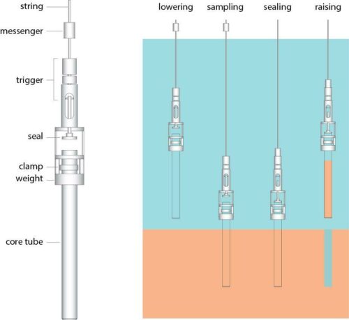
Gravity core recoveries are generally limited by equipment design and sediment conditions. Most standard gravity driven corers rarely recover more than 4–5 m in upper to lower slope sediments. The ratio of penetration to recovery for most gravity core devices ranges from 50 to 100% and will depend heavily on the venting system design and internal diameter.
Gravity coring tools generally include deployment of a weighted steel pipe dropped into the seabed from a height of 10–20 m. The conventional open barrel gravity corer is a hollow tube (barrel) attached to a vented weight (core body).
Key elements of the gravity corer (drop corer):
- simple construction
- low investment cost
- adjustable weights and core barrel
- limited sample length (4–6 m)
- easily handled – few personnel required (1–3)
- ideal for soft/semi-hard sediments
- no depth limitations
- no external energy source – uses gravity
- operational in a large weather window
- high sampling frequency (cost effective)
- worldwide availability
Piston corer
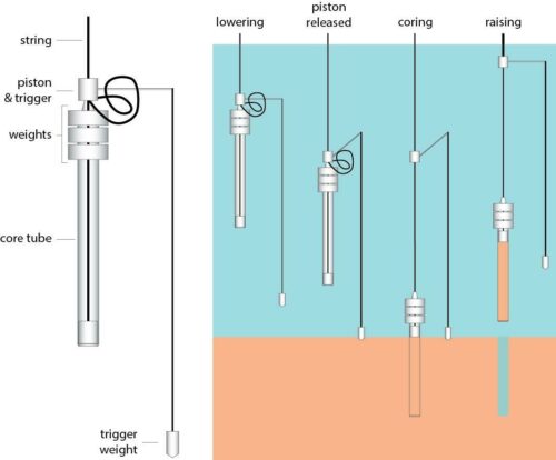
The piston corer is similar to the open barrel gravity corer except it utilizes a trigger weight and piston. The tripped piston corer free falls a given distance while an internal piston remains stationary on the sea floor as the core barrel penetrates the sediment. The stationary piston creates suction which minimizes wall drag and sediment disturbances. The piston corer was primarily designed for deep-water fine-grained sediments.
Key elements of the piston corer:
- simple construction
- low investment costs
- fairly easily handled – few personnel (1–3)
- ideal for soft/semi-hard sediments
- no depth limitations
- no external energy source
- wide weather window
- moderate sampling frequency (less cost effective cf gravity corer)
- worldwide availability
Vibrocorer
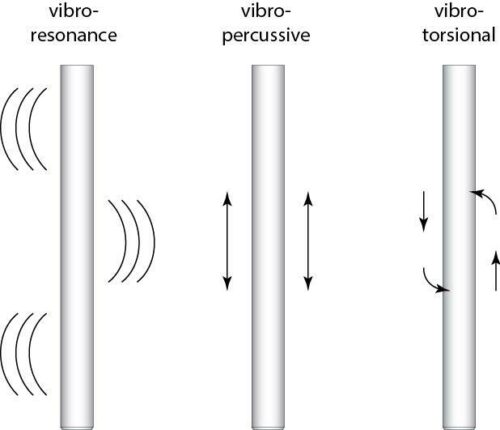
Vibrocorers are pipes with air pressure or electric vibrating heads. The head vibrates at high frequency and low amplitude to facilitate sediment penetration. The original air driven devices have limited water depth capabilities, generally <50 m.
The newer electric vibrocore devices can work in depths up to 1500 m (Rossfelder VT-1 model). Although initially designed to collect samples in shelfal coarser grained lithologies, vibrocorers have also been used to collect compacted and slightly cemented sediments which conventional gravity driven devices will not penetrate.
The corer launching and recovery system is very important to undertake a safe and efficient operation, as well as minimize core sample disturbance. Several systems (see Fugro Alluvial Offshore Limited Website for details; www.alluvial.co.uk) are designed to bring the corer on deck with minimal effort by the crew. A high speed winch, capable of retrieving the corer at speeds of 100/300 m/min, is critical in deep water marine operations.
Key elements of the vibrocorer:
- penetrate hard/sandy sediments
- penetrate by vibration/hammering the barrel into the sediment
- not easy to handle, due to its size, docking methods and use of derrick/crane
- moderate investment cost
- requires more operating personnel (2–5), including engineer
- external (electric) energy source/air pressure from vessel
- depth limitations (most equipment limited to <400 m)
- narrow weather window
- limited sample frequency
- worldwide availability
Push corer
The push corer system has a spring loaded or mechanical arm that pushes a tube into the sediment. It is applicable generally only to environmental studies as it recovers only the top 0.5–1.0 m of unconsolidated sediment. In deep waters the system is typically handled by use of an ROV. It is rarely used for sampling of shallow cores for geochemical exploration purposes.
Key elements of push coring:
- mainly used to sample for environmental analysis
- spring loaded or mechanical arm pushes tube into sediment
- short cores (0.5–1.0m)
- limited to unconsolidated sediments
- in deep waters it is employed by using a ROV
Operational considerations
Corer positioning
Locating the corer during deep water coring operations (>1000 m) is very important. There are several acoustic systems currently available to assist in locating the corer while deployed, the most commonly used for geochemical operations is the Ultra Short Baseline (USBL) system. It can provide an accuracy of 5–10 m, depending on the water depth, the specific USBL system, and the operator.
Although the position of the core body relative to the target can be monitored, placing the corer on the feature is another matter; it is very difficult with the current deep water coring systems. Trying to move a weighted corer in water depths of 1500 m or more from a surface vessel is extremely difficult; the corer body will not move in direct response to the vessel movement due to the large distance between the two. To date there is no cost effective system to position the corer directly on the targeted feature.
Real time seismic
Obtaining a real time image of the targeted feature will greatly enhance a seabed geochemical program. It provides sufficient detail to delineate the feature and helps to define its relationship to active hydrocarbon seepage. In addition, it provides a well defined target location.
An effective real time seismic system requires minimal set up time and sufficient power to obtain good penetration and target resolution. Hull mounted systems are ideal since they do not require launch and retrieval. A focused beam with sufficient power is required to obtain good imaging in deep water.
Survey vessel
The kind and size of vessel required for a safe and efficient marine sampling program depends on several physical and operational factors, such as:
- need for on-site real-time seismic (side scan sonar/shallow seismic etc)
- need for USBL
- selected sampling device/corer type (corer docking device/space on deck)
- length of core barrel (space on deck)
- likely weather/climatic conditions (relevant to vessel design, height of freeboard/ corer docking mechanism etc)
- number of coring/sampling personnel (accommodation)
- distance between survey sites and from port of mobilization (operational range & speed of vessel)
- winch type (high speed winch for deep waters)
- storage capacity (number of freezers accommodated onboard)
- onboard monitoring facilities
Within the market for survey vessels a number of contractors supply vessels of suitable size and shape, equipped with the necessary positioning and communication equipment, and compliant with the oil industry’s strict HSE/QAM requirements.
A minimum coring crew should comprise the following personnel (double crew for 24 h operations):
- contractor’s party chief
- 1–2 technicians for gravity/piston coring
- 1 engineer, 1–3 technicians for vibrocoring
- 1 engineer, 1–3 technicians for Selcore® operation
Sediment sample collection
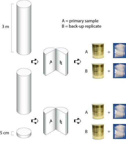
The sediment hydrocarbon content, both gas and liquids, will vary with depth within the sediment core. Multiple sub-samples from the full core, ranging from the deepest portion to no less than 1 m from the core top, will provide details on the hydrocarbon variability and, often, location of the oxic/anoxic boundary and sulphate reducing zone. At least 2 sections should be collected for each 2.5+ m core (Abrams et al. 2002, 2004, 2007).
Replicate back-up samples should be collected and stored until the primary samples have been safely delivered for analysis. As well as providing back-up against loss/damage of primary samples in transit, the replicates can be used for quality control assessment of analyses. The core processing protocols and storage container recommendations are discussed in greater detail in the next section.
Key recommendations for sample collection
- sampling should be in the anoxic part of the core – this is particularly important in gas surveys as most degradation of gas, and organic matter in general, takes place in the upper oxygen-rich part of the sediment (the oxic/anoxic boundary may vary with sediment type and climate but is typically ~1.0 m below seafloor)
- samples should be collected from the base section of the core (minimum requirement) or from multiple depths within entire core (preferably at least three sections per core, unless core is <2.5 m long)
- sample visible hydrocarbons in the core
- sample sand horizons in the core
- sample sections of distinct odour (petroleum, H2S etc)
- sample any visible gas hydrates
- collect replicates, to be held on site until primary samples have arrived at the analytical facilities
Onboard processing
Once the sediment has been cored and the corer brought on deck, a series of important procedures must be followed to process the sediments quickly, efficiently, and consistently. The core liner with the sediment sample should be removed immediately and the core cut into sections by the deck staff, avoiding contamination from lubricants and/or exhaust.
Each core section should be taken to the core preparation laboratory immediately for sub sampling and processing, in accordance with the pre-survey specifications.
General procedure for offshore core sampling
- retain the liner from the core barrel
- measure core length to ensure sufficient penetration
- extrude sediment for geochemical sampling from core liner
- cut off base part for geochemical samples
- describe sediment if required
- collect geochemical sample(s) in clean cans/bags
- conserve geochemical samples
- preserve remainder of core
- if the analytical program is only focused on analysis of extractable HC, samples can be sampled in alumina foil (dull side to samples) and zip bags
- cans should be flushed with inert gas (i.e. N2) before sealing, and then stored lid-down
- backup/replicate samples should preferably be retained – and stored separately
- samples should be stored at a minimum of −20°C (both onboard the vessel and in the laboratory) to reduce bacteriological activity
Sample types
Volatile sample preservation
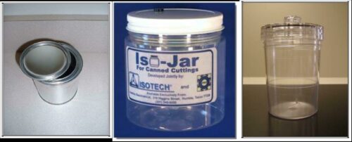
The most common container used for the collection of volatile hydrocarbons and non-hydrocarbon gases is the compression lid, non-coated, metal can, of approximately 500 mL size. The two key problems with these cans are rusting and leakage. They rust quickly and thus cannot be used to store marine sediment samples beyond a few months.
The compression lids are subject to leakage issues as the lids may loosen due to increasing pressure or mechanical disturbance. A plastic screw-cap container with built-in reusable septum and cap sealing gasket such as Isotech ISO-JARS™ (Isotech Laboratories, Illinois) or the EGI (Energy & Geoscience Institute, University of Utah) patent pending disrupter container are ideal for storing and subsequent gas sampling of sediments. Both of these containers have been rigorously tested for leakage issues and do not rust.
The amount of sample, volume of water and headspace are important factors in optimising the extraction of small concentrations of migrated hydrocarbons from marine sediments. The type of water added and inert vs air headspace are also important factors.
Currently, each contractor has their own preferred method: EGI use equal volumes of sediment sample, water and gas headspace; the Texas based TDI Brooks International’s procedure is based on a 500 mL compression lid, non-coated, metal can, with approximately equal volumes (170 mL) of sediment, clean seawater, and nitrogen headspace flush, together with the addition of sodium azide ad a biocide; whereas the Norwegian SGS/Geolab Nor uses a similar size can (500 mL) but containing ~375 mL of sediment and no water or inert gas headspace flush.
Compression metal cans appear to be the most cost efficient and suitable for most sampling (so long as analyses are performed soon after), although Isojars provide more reliable sealing and do not rust.
Non-volatile hydrocarbon samples
The ideal container for HMW hydrocarbon sediment samples is a clean glass jar. Unfortunately breakage is an issue during transit, so they are not the best containers for remote area seabed geochemical surveys. Plastic bags are more practical for wet marine samples, however, contaminants from the plastic bags include oleamide, fatty acids (C16 and C18) and Irganox (an antioxidant), as well as various plasticisers. These components do not impact the overall interpretation but may appear as major peaks during screening GC analysis. The oleamides and irganox will be present in total extract GC chromatograms even if a non-polar extraction solvent is used and no derivitizing agent applied to the sample.
One way to get around the plastic bag contaminants is to wrap the sediment sample in aluminium foil prior to placing in the plastic bag. This will keep the sediment separate from the plastic bag reducing potential contamination issues. Not all aluminium foil is sufficiently clean to use for sediment sampling. Some commercial aluminium foil may contain coating to prevent sticking which will affect the solvent extraction results. The recommendations for the collection and onboard processing of the non-volatile (HMW hydrocarbons) samples are as follows:
- Collect at least 250 mL of sediment using clean spatulas;
- Place the sediment on clean aluminium foil, lightly wrap sediment sample in aluminium foil;
- Flatten the sediment sample into a pancake making sure there are no air pockets;
- Place the flattened sediment sample package in a labelled standard plastic bag (Ziploc);
- Sample numbers should be written clearly on sample bags with a permanent marker and a paper tag placed inside the bag inscribed with the sample number.
Water surface (slick) sampling
The most common methods currently used by the industry to obtain an ocean surface slick sample are simply collecting a surface water sample directly into a receptacle or placing an absorbent material such as Nybolt fibre (silicone based absorbent material) or Gore-based systems such as the AGI Universal Sampler.
The simple water sampling method is limited to relatively robust slicks, since collecting sufficient ocean surface petroleum in thin microlayer sheen has proven to be very difficult (Abrams et al. 2002). The following section summarizes the most common material/equipment used for surface sampling.
Nybolt Fiber
Nybolt fibre absorbent material has limitations due to the sampling process. It has to be in direct contact with the oil in order to collect an adequate amount of hydrocarbons and a representative sample. The amount of seep material that can be collected is therefore limited by surface area.
Gore technology
AGI Universal Samplers can be used for sampling oil slicks on water. They are constructed of GORE-TEX ePTFE® (polytetrafluoroethylene) and filled with sorbent and have previously been used as passive soil samplers. Since ePTFE has a chemically inert microporous hydrophobic structure, it allows vapour phase transfer of hydrocarbons but not water.
The sorber modules are analyzed by thermal desorption coupled with gas chromatography – mass spectroscopy. Potentially they can sample the full range of hydrocarbons from C2 to C28+, although recovery declines with decreasing vapour pressure (i.e. increasing b.p.).
Model 5080 General Oceanics oil sampling net kit
The General Oceanics (GO) samplers were developed in conjunction with the U.S. Coast Guard Marine Safety Laboratories for spill collection, transportation and geochemical identification. The Model 5080 device is made up of a highly porous TFE-fluorocarbon polymer net which is reputed by the manufacturer to capture up to 10 times the volume of oil compared to the traditional water sampling methods.
The polymer net is passed through the surface ocean oil slick using a pole and disposable ring to collect a petroleum sheen sample. The net is removed from the disposable ring and handle and placed in a 4 fl oz glass jar with Teflon lined cap for storage and transportation.
Equilon-SEPCO sheen sorbent sampler
The Equilon-SEPCO Sheen Sorbent Sampler was collaborative design by Equilon and SEPCo (US Patent Number 6,237,431 B1). It uses chemically treated tetrafluoroethylene, polypropylene or polytetrafluoroethylene strips, with a large surface area, which float and do not disperse the sheen on contact, according to Equilon studies.
The strips are chemically clean and do not interfere with the geochemical fingerprinting. The sampler is wrapped in a cover which dissolves on deployment, and the maximum sorbent material surface area is then exposed to the slick using a rod and reel system, after which it is placed in a special container for shipping. The sorbed petroleum is recovered using standard solvent extraction prior to analysis.
Dembicki Teflon Squid
The Dembicki Teflon Squid is a teflon bundle which is placed in a slick using a rod and reel system similar to the AGI and Equilon-SEPCO samplers. The sampler is placed in a glass vial and kept cool or frozen until analysis, when standard solvent extraction is used to recover the hydrocarbons.
Surface skimmers
Ocean surface skimmers are designed to collect thin petroleum layers on the ocean surface. Most surface skimmers have been designed for the collection of large volume oil spills. The Marine Sciences Institute at the University of California Santa Barbara (UCSB) has designed a system to collect thin petroleum sheens. It requires very calm conditions but can sample a large area (which provides an average composition across a slick).
A rotating metal drum collects the thin layer of petroleum, which is then moved into a holding tank. The technique has not been assessed for potential hydrocarbon compositional fractionation effects, and there is a potential issue with thorough cleaning of the drum on-board between sampling of different slicks.
Onshore sampling
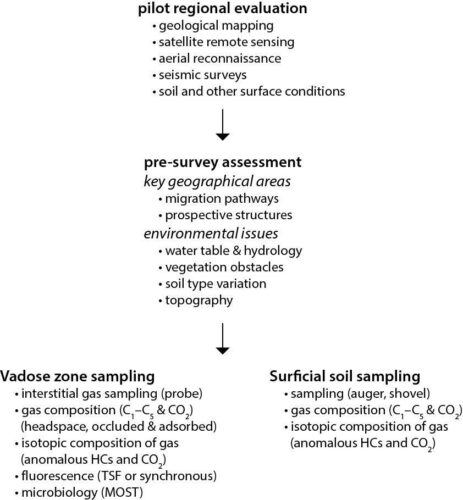
Onshore surface geochemical surveys can be problematical because of greater variability of surface conditions (climate, vegetation, topography, water table and soil conditions). A multi-level evaluation starting with a regional reconnaissance using satellite, airborne and geological maps is recommended. The type of sampling program (grid vs site specific) and analytical program will depend on the pre-survey evaluation.
Soil or outcrop sampling involves the collection of a soil or sediment sample from a designated depth below the soil-atmosphere interface, which is typically 0.5–1.0 m below the surface. The sampling can be accomplished by a variety of devices such as an auger (hand or powered), split spoon sampler or simply by digging a hole. A specified amount of sample (typically ~0.5 L) is collected and placed in a specially modified can, air-tight bag, Isotech ISO-JARS™ or similar.
The most commonly applied sampling techniques for onshore coring are:
- push coring
- manual auger
- hydraulic hammer
- mechanical hammer
Push corer
These are generally fairly small devices which are easy handled and portable. They are based on a spring loaded or mechanical arm which pushes the coring tube into the sediment. They work in most terrains, but are limited to unconsolidated sediments and short cores (0.5–1.0 m), and are not routinely used for sampling soil. They allow high sampling frequency and are thus cost effective.
Manual auger & hydraulic/mechanical hammer
Manual augers are the most frequently used coring devices onshore; they are easy to transport (in a back pack or in a van) and handle. There is a variety of designs, but they are typically screwed/twisted into the soil by man power.
They work in most terrains and permit high frequency sampling, but are restricted to soft sediments/soil and short cores (<1 m). In contrast, hydraulic or mechanical hammer devices are large and will normally need to be transported in a van. They will also require an external energy source in the form of electricity or pressurized air for actuation of the core barrel hammer.
Remote sensing & passive sampling
In areas covered by heavy vegetation (woodland, rainforests etc.), deserts, tundra or other remote areas with limited access for conventional sampling equipment, remote sensing or passive sampling technologies can be used for surface geochemical exploration. There is a wide variety of methods ranging from satellite imaging to adsorbents and probes. The most frequently applied technologies are:
- Synthetic Aperture Radar (SAR)
- Airborne Laser Fluorescence (ALF)
- microbial prospecting (for oil and gas)
- Gore™ Technology probes
- PETREX® Technology
- soil vapour sampling
- active adsorbent gas-sieve analysis
Synthetic Aperture Radar (SAR)/Airborne Laser Fluorescence (ALF)
Synthetic Aperture Radar (SAR) and Airborne Laser Fluorescence (ALF) have become standard tools for petroleum system validation in offshore frontier exploration areas. SAR and ALF sensors use radar to build an image from satellite/plane-borne detectors. Incident radar waves are emitted at an oblique angle to the ocean surface and the backscatter signal is controlled by the state of the sea surface. The dampening of ocean surface capillary waves by oil slicks, natural films, biological material or physical processes such as currents and winds will produce an anomalously low backscatter. Because not all wave dampening features are related to petroleum seepage, contractors use several criteria to rank anomalies:
- repeatability (temporal)
- shape (dog-leg, blob or tadpole)
- dimensions
- thickness
- relationship to subsurface and near-surface features
Microbial prospecting (MicroPro)
In certain geological settings the measurement of hydrocarbons to evaluate petroleum seepage may not be effective, and near-surface microbial populations have been used as an alternative for many years. The current near-surface microbiological methods include GeoMicrobial’s Microbial Oil Survey Technique (MOST) and MicroPro GmbH Microbial Prospection for Oil and Gas (MPOG).
Both methods assume there is a direct relationship between the hydrocarbon concentrations in near-surface sediments and particular microbial populations, so that elevation of the latter can be used as a reliable indicator of light hydrocarbon leakage from individual petroleum accumulations.
The microbial prospecting technology is based on detection of anomalies in microbial distributions in soil samples and has proven effective even where complex reservoir geology is involved. It has the advantage that sampling is simple (limited equipment is required), environmentally friendly and unaffected by local disturbance.
The method has been used to distinguish between oil reservoirs, gas reservoirs and oil bearing structures with a gas cap. It is not influenced by fractures, overlying salt or other geological structures.
Areas of application include both onshore (e.g. permafrost and desert) and offshore sites. Sampling is carried out onshore using a hand auger at a depth of ~150 cm, whereas offshore gravity/vibration corers or a grab sampler are used to obtain sediment from ~30 cm below the seafloor. ~100 g of soil/sediment is stored in airtight sterile sampling bags for preparation and analysis at the laboratory.
A new DNA based assay method called SARD (serial analysis of ribosomal DNA) has been developed, which appears to have potential but needs further testing before adoption as a routine surface geochemical method.
Gore samplers
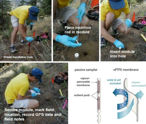
An important factor in the success of the Gore-based samplers is the unique hydrophobic adsorbent encased in an expanded polytetrafluoroethylene (ePTFE) membrane. The membrane repels soil particles and liquid water, but its unique pore structure provides unimpeded access of the molecules of interest to the adsorbent. This allows the module to cope with many local and regional variations in soil character and to be placed directly in dry or saturated soils or in water up to a depth of ~10 m (water penetration is likely at greater depth).
Hence it is a tool which can image a charged reservoir extending from dry land through a tidal area into a shallow bay. The technology, supplied by AGI (Advanced Geochemical Imaging LLC) as their Universal Sampler, is environment friendly, and the sampler module is designed to fit inside thermal desorption apparatus for analysis by GC-MS (C2–C20 range). The sampler can also be used on water slicks.
Installation and retrieval of sorber modules at depths of 0.5–1.0 m in soil, rock or permafrost (using hand drills for hard substrates) is rapid, easy and inexpensive. Exposure time depends on the application and can vary from 15 min. for environmental water sampling to two months in rock over buried ore deposits. Typical soil exposure time for petroleum exploration is 17–21 days.
For deeper offshore exploration, a sampler can be inserted in an ocean bottom core (normally obtained by conventional gravity, piston or vibrocorer) in a sealed glass jar and processed like any other field sample. Two sorber pods are included so replicates are available for verification of potentially anomalous results.
PETREX® technology
The PETREX® technology is in general terms quite similar to that of the AGI Universal Sampler, in that an adsorbent is used and analysis is by thermal desorption MS. However, because the adsorbent is charcoal, care has to be taken with placement and environmental conditions to avoid deactivation by moisture.
In the PETREX® sampler the activated charcoal is fused to a ferromagnetic wire within a glass tube. For soil sampling, the tube is buried in a shallow hole for up to 2–3 weeks, open end downward, whereas for surface sediment sampling the tube can be placed in a gas permeable but water-tight plastic bag. During this period the samplers will gradually adsorbed gas/vapour migrating to the surface until equilibrium between the gases and the charcoal is reached.
As with the GORE technology, the PETREX® system is easily handled and installed with simple hand tools and is environment friendly.
Gas sieve technology
This less well known exploration technique is used by a limited number of contractors (mainly based in the USA and Canada). It is based upon driving a sampling system 10–20 cm below ground level, where a vacuum system is used to lift 1 L of soil vapour to the surface and across a gas sieve, so is confined to onshore prospecting.
The gas sieve is small, light and easily shipped equipment which collects and concentrates C1–C18 hydrocarbons present in the soil vapour, allowing direct analysis of these compounds. Each sampling event requires about 7 min. and an individual gas sieve.
References
General
Abrams M.A. (1992) Geophysical and geochemical evidence for subsurface hydrocarbon leakage in the Bering Sea, Alaska. Marine & Petroleum Geology 9, 208–221.
Abrams M.A. (1996) Distribution of subsurface hydrocarbon seepage in near surface marine sediments, In (ed. Schumacher D., Abrams M.A.) Hydrocarbon migration and its near-surface effects. AAPG Memoir 66, 1–14.
Abrams M.A., Segall M.P (2002) Surface geochemistry calibration study: phase I. EGI Research Report 2002-50500725.
Abrams M.A., Francu E., Dahdah N.F., Logan G.A. (2004). EGI surface geochemistry calibration study. Phase II report. EGI Technical Report 2004-50501003.
Coring
Horvitz L. (1972) Vegetation and geochemical prospecting for petroleum. AAPG Bulletin 56, 925−940.
Horvitz L. (1981) Hydrocarbon prospecting after forty years. In (ed. Gottleib B.M.) Unconventional methods in exploration for petroleum and natural gas II, 83−95. Southern Methodist University Press, Dallas.
Horvitz L. (1985) Geochemical exploration for petroleum. Science 229, 812−827.
Mello M.R., Babinski N.A., Penteado H.L.B., Meniconi M.F.G. (1994) Application of surface geochemistry and microbiological methods in a desert environment: The experience in Ghadames Basin, Libya. Abstracts AAPG Hedberg Research Conference on near-surface expression of hydrocarbon migration. Vancouver BC, Canada, April 1994.
Mello M.R., Goncalves F.T.T., Babiunski N.A., Pellon F.P. (1996) Hydrocarbon prospection in the Amazon Rain Forest: Application of surface geochemistry, microbiological and remote sensing. In (ed. Schumacher D., Abrams M.A.) Hydrocarbon migration and its near-surface expression. AAPG Memoir 66, 401−412.
Schiener E.J., Stober G., Faber E. (1985) Surface geochemical exploration for hydrocarbons in fffshore areas - principles, methods, and results. In (ed. Thomas M.B. et al.) Petroleum geochemistry in exploration of the Norwegian Shelf, 223−238. Graham and Trotman.
Thrasher J., Fleet A.J., Hay S.J., Hovland M., Düppenbecker S. (1996a) Understanding geology as the key to using seepage in exploration: The spectrum of seepage styles. In (eds Schumacher D., Abrams M.A.) Hydrocarbon migration and its near-surface expression. AAPG Memoir 66, 223−242.
Thrasher J., Strait D., Alvarez Lugo R. (1996b) Surface geochemistry as an exploration tool in the South Caribbean . In (ed. Schumacher D., Abrams M.A.) Hydrocarbon migration and its near-surface expression. AAPG Memoir 66, 373−384.
Woodward C.A., Sloss C.R. (2013) Coring and augering. In (ed. Schroder J.) Treatise on Geomorphology, 119–137. Academic Press, Elsevier Inc, San Diego.
Soil vapour technology
Hewitt (1995) Enhanced preservation of volatile organic compounds in soil with sodium bisulfate. USA Cold Regions Research & Engineering Laboratory Special Report 95−26.
Hewitt A. (1996) Establishing a relationship between passive soil vapor and grab sample techniques for determining volatile organic compounds: US Army Corps of Engineers, Cold Regions Research & Engineering Laboratory Special Report 96−14.
Hewitt A.D. (1997) Chemical preservation of volatile organic compounds in soil. Environmental Science & Technology 31, 67−70.
Hewitt A.D. (1998) Laboratory study of VOC partitioning: Vapor/aqueous/soil. USA Cold Regions Research & Engineering Laboratory Special Report 98−3.
Hewitt A.D. (1999) Storage and preservation of soil samples for volatile compound analysis. U.S. Army Corps of Eng., Cold Regions Research & Engineering Laboratory Special Report 99−5.
Hewitt A.D., Lukash N.J.E. (1996) Obtaining and transferring soils for in-vial analysis of volatile organic compounds. USA Cold Regions Research & Engineering Laboratory Special Report 96−5.
MicroPro technology
Baum MG., Wagner M. et.al. (1997). Application of surface prospecting methods in the Dutch North Sea. Petroleum Geoscience 3, 171−181.
Wagner M. (1966) Ergebnisse der mikrobiologischen Prospektion im Küstenbereich der Ostsee. In (ed. Malek, Schwartz) Vorträge des Internaltionalen Symposium Erdölmikrobiologie, Brno 1964. Akademie Verlag, Berlin.
Wagner M., Wagner M. (1999a) Microbial prospection for oil and gas - case histories on- and offshore. 1999 Offshore Mediterranean Conference Proceedings 2, 1061−1067. Ravenna, Italy.
Wagner M., Wagner M. (1999b) Case histories of microbial prospection for oil and gas onshore and offshore in north-west Europe. In (ed. Schumacher D., Len Le Schack) Application of surface exploration methods to exploration, field development and production. AAPG Studies in Geology 47 & SEG Geophysical References Series 11, 453–479.
Wagner M., Wagner M., Rasch H.J., Piske J., Baum M. (1998) MPOG - Microbial prospection for oil and gas. Field examples and their geological background. 1998 Offshore Mediterranean Conference Proceedings AO-05, 118−121. Cracow, Poland.
Gore technology
Coleman D.D., Meents W.F., Liu C.L., Keogh R.A. (1977) Isotopic identification of leakage gas from underground storage reservoirs – a progress report. Illinois State Geological Survey Report 111, 10.
Hewitt A.D., Lukash N.J.E. (1996) Obtaining and transferring soils for in-vial analysis of volatile organic compounds, USA Cold Regions Research & Engineering Laboratory Special Report 96-5.
Klusman R.W. (1993) Soil gas & related method for natural resource exploration. John Wiley & Sons Ltd, Chichester. 483 pp.
Klusman R.W., Saeed M.A. (1996) Comparison of light hydrocarbon microseepage mechanisms. AAPG Memoir 66, 157−166.
LaPlant L. (2002) Innovative strategy to locate VOC sources deep in the subsurface. Proceedings 3rd International Conference on Remediation of Chlorinated and Recalcitrant Chlorines.
Harrington P., Lee N., Goold D., Stolpmann H. (2005) Surface geochemistry: a case study of new risk reduction technology applied in Algeria. 2nd EAGE North African/Mediterranean Petroleum & Geoscience Conference & Exhibition, Algiers.
Potter R.W., Harrington P.A., Silliman A.H., Viellenave J.H. (1996) Significance of geochemical anomalies in hydrocarbon exploration: one company’s experience. AAPG Memoir 66, 431−439.
Viforeanu A., Wells W., Hodny J.W. (2003) Passive geochemical survey leads to dry gas discoveries. World Oil 224(6), 53–59.
Other indirect methods
Foote R.S. (1996) Relationship of near surface magnetic anomalies to oil and gas producing areas. AAPG Memoir 66, 111−126.
Horvitz L. (1972) Vegetation and geochemical prospecting for petroleum. AAPG Bulletin 56, 925−940.
Tedesco S.A. (1988) The use of radiometrics with soil gas geochemistry to define and delineate Hoing Sandstone Reservoirs in the Western Illinois Basin. Association of Petroleum Geochemical Explorationists 4, 82−101